Dielectrophoretic particle chromatographie (DPC) at preparative scale (SPP 2045)
Dielectrophoretic particle chromatography (DPC) is a separation method for a variety of microparticles, these can be of biological, synthetic or natural origin. By influencing the particles with inhomogeneous electric fields, specific residence times or separation rates for different particles are obtained. The method is suitable for the analysis and separation of microparticles. In addition, the scalability of electrode-based dielectrophoresis using low-cost printed circuit boards (PCB) is investigated.

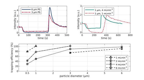
Trapping of monodisperse PS particles of different size and at different flow rates in the PCB based setup. All data are obtained at 15 kHz and 75 Vpp. Voltage was applied after 30 s and turned off at 300 s. (A) Fluorescence signal of 3 μm and 6 μm PS particles at 6 ml/min volume flow. (B) Fluorescence signal for 1μm particles at 1 and 4 ml/min. (C) Monodisperse trapping efficiency as a function of particle size and flow rate.

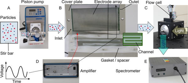
Overview of the experimental setup based on PCB. The particles are suspended in water, stirred by a magnetic stirrer, and pumped by a piston pump (A) into the separation device (B). The separation chamber is formed by two PCBs on which the electrodes arrays are located. A silicone gasket (0.5 mm thickness) defines the flow path of the suspension as well as the height of the channel. Cover plates made of polypropylene and screws are used to press the components onto each other. The electrodes are connected to an amplifier which provides a sinusoidal voltage to operate the device (D). The suspension leaving the channel is flowing into a flow cell (C) that is coupled to a light source. The resulting fluorescence signal is recorded by a spectrometer (E) connected to a computer.

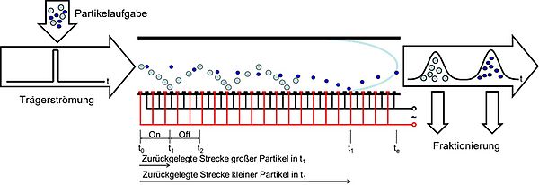
Workflow of dielectrophoretic particle chromatography (DPC). (A) Top view of the microfluidic device (sketch). (B) The microfluidic separation column (side view, height h = 80 μm and electrode width/spacing d1 = d2 = 100 μm ) is continuously flushed with a carrier fluid. Once per experiment a particle suspension is injected. The device is used for two different types of experiment. (I) The crossover frequency of particles is determined using field-flow fractionation (FFF) at a fixed frequency f by comparing the elution profiles with and without applied voltage (V0) (C). The obtained particle characteristics where used as input parameters for a full-scale simulation model realized in COMSOL Multiphysics to find suitable process parameters (D). (II) Eventually, the set of process parameters is used as starting point for experiments to achieve a chromatographic separation by using frequency-modulated ( f = f (t) ) DPC (E).

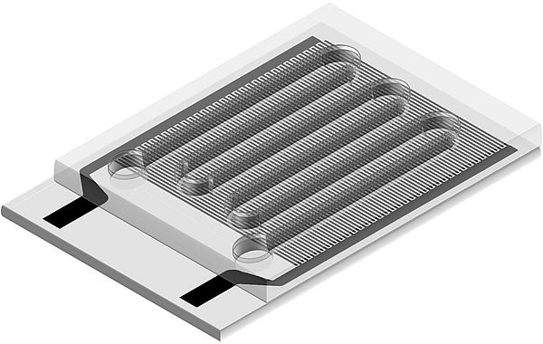
Image: Microfluidic device for dielectrophoretic particle chromatography. A constant fluid flow carries particles through a meandering channel. The bottom of the channel is given by an array of electrodes on top of a transparent substrate.
In current publications, most DEP separators are microfluidic devices and are consequently only capable of handling volume flows in the µLh-1 or lower mLh-1 range. These separators work by either using selective trapping of particles or spatial separation of different particles. This type of operation can be feasible for highly valuable products as proteins or cells and can be even considered as high throughput. However, for less valuable products or high quantities an increase in throughput is necessary. Since the DEP force scales with the gradient of the electric field squared, it is important to maintain the magnitude of the gradient during the scale up of the device. For microfluidic setups scale up by numbering up is considered as an option, but since the fabrication of microfluidic devices often requires clean-room techniques and small setups are challenging to handle, setups with larger dimensions are a focus of current research. One way to up-scale DEP separators up, is by using macroscopic insulating structures as glass beads, meshes or alumina foams to scatter the electric field and thus generate local field minima and maxima. This approach is called insulator-based dielectrophoresis (iDEP). The high-throughput iDEP approaches, however, need high voltages since the electrodes themselves are separated by the insulator which additionally blocks the fluid pathway resulting in an increased pressure drop. The insulating material is also challenging to clean after processing the materials. In contrast, electrode-based DEP (eDEP) often use electrode arrays to generate inhomogeneous electric field. eDEP separators are not used as high throughput separators yet as large electrode arrays are expensive and time consuming to fabricate within the clean-room.
The aim of our work is to develop novel tools for addressing both separation tasks, high selectivity and high throughput. The former should be used by developing a novel chromatographic technique which is utilizing dielectrophoresis to generate trap and release cycles as this was analytically shown to be favorable for high selectivity. Although chromatographic techniques are rare in the field of DEP; they might be an option for realizing highly specific separations. As a second step the upscaling of eDEP devices should be addressed, since this is a bottleneck of current electrode-based approaches. Additionally, when scaling up, the specific costs for the setups should massively decrease to favour the applicability of macroscopic eDEP devices.
Project-relevant publications
J. Giesler et al. (2022). Electrophoresis. https://doi.org/10.1002/elps.202200131
J. Giesler et al. (2021). Scientific Reports 11(1), 16861. https://doi.org/10.1038/s41598-021-95404-w
J. Giesler et al. (2020). Micromachines 11(1), 38. https://doi.org/10.3390/mi11010038
Contact:
Giesler, Jasper, M. Sc.
Room UFT 2110
Fon: 0421- 218 - 63495


